Quick Specs of Cisco ISR4451-X/K9
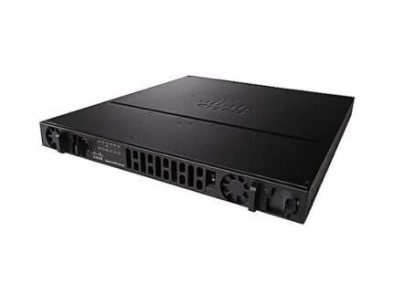
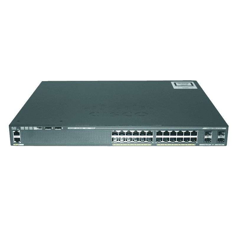
Figure 1 shows the appearance of Cisco ISR4451-X/K9.
Table 1 shows the Quick Specs.
| Product Code |
Cisco ISR4451-X/K9 |
| Aggregate Throughput |
1 Gbps to 2Gbps |
| Total onboard WAN or LAN 10/100/1000 ports |
4 |
| RJ-45-based ports |
4 |
| SFP-based ports |
4 |
| Enhanced service-module (SM-X) slot |
2 |
| NIM (Network Interface Modules) slots |
3 |
| Onboard ISC slot |
1 |
| DDRM (data plane) |
2 GB (default) / 2 GB (maximum) |
| DDRM (control/services plane) |
4 GB (default) / 16 GB (maximum) |
| Flash Memory |
8 GB (default) / 32 GB (maximum) |
| Power-supply options |
Internal: AC, DC (roadmap) and PoE |
| Rack height |
2 RU |
| Dimensions (H x W x D) |
88.9 x 438.15 x 469.9 mm |
Product Details of Cisco ISR4451-X/K9
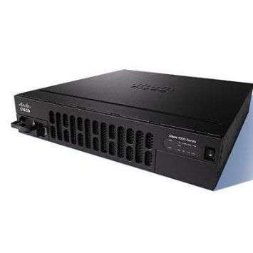
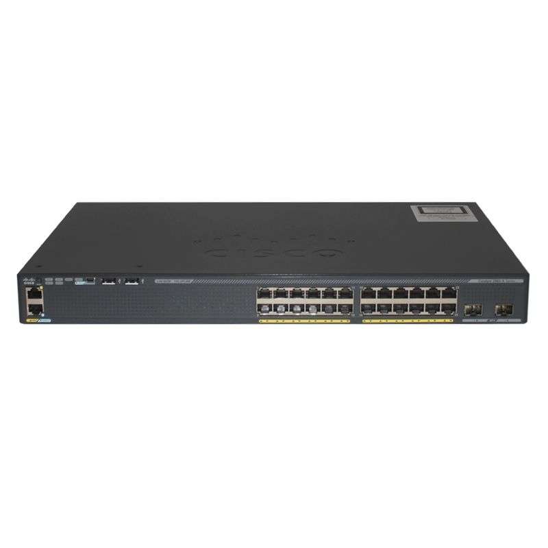
Figure 2 shows the front panel of Cisco ISR4451-X/K9.
Note:
| ① |
AC power supply unit (PSU0) |
④ |
Router power On/Off switch |
| ② |
Router fan tray |
⑤ |
LEDs |
| ③ |
AC power supply unit (PSU1) |
|
·Router fan tray is hidden behind removable bezel.
·LEDs include 12 indicators.
Table 2 shows the LED descriptions.
| LEDs |
Represents |
Color |
Description |
| PSU |
Power Supply Unit (P0 and P1) Status |
Green |
PSU is on and is providing power. |
| Amber |
PSU is on but with errors or in a failure condition. |
| Off |
Power supply is turned off. |
| GE POE |
Internal PoE Daughter Card Status |
Green |
PSU is installed and providing power |
| Amber |
PSU is installed but in a failure condition. |
| Off |
PSU is off. |
| FLASH |
System Flash Status |
Blinking Green |
Compact flash/eUSB flash is present and currently being accessed. |
| TEMP |
Temperature Status |
Solid green |
All temperature sensors in the system are within acceptable range. |
| Amber |
One or more temperature sensors in the system are outside the acceptable range. |
| Off |
Temperature is not being monitored. |
| PWR |
System Power |
Green |
System power is on and functioning correctly. |
| Green blinking |
System power is in the process of shutting down. |
| Amber |
System power is up, but low level initialization failed. |
| Amber blinking |
System power is up, but the system failed to come out of reset. |
| Off |
System power is off. |
| POE BOOST |
Power Over Ethernet Boost Mode |
Green |
Two PoE power supplies are installed and operating in boost mode. |
| Off |
This can mean one of the following:
·No PoE PSU installed.
·One PoE PSU installed.
·Two PoE PSUs installed and operating in redundant mode. |
| ISC |
ISC Slot Status |
Green |
PVDM4 is present and enabled. |
| Amber |
Initialized with error. |
| Off |
Not present. |
| FAN |
Fan Status |
Green |
All fans are operating. |
| Amber |
One fan has stopped working. |
| Blinking Amber |
Two or more fans have stopped working, or the fan tray has been removed. |
| Off |
Fans are not being monitored. |
| STAT |
System Status |
Solid green |
System operating normally. |
| Blinking amber |
BIOS/Rommon is booting. |
| Amber |
BIOS/Rommon has completed booting, and system is at Rommon prompt or booting platform software. |
| Off |
System is not out of reset or BIOS image is not loadable. |
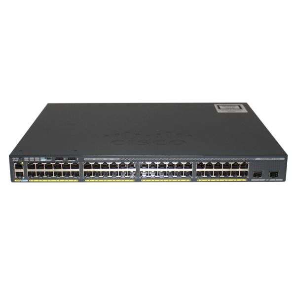
Figure 3 shows the back panel of Cisco ISR4451-X/K9.
Note:
| ① |
USB Type A port |
⑤ |
Auxiliary port |
| ② |
GE management port |
⑥ |
GE Ports |
| ③ |
USB Type B mini port |
⑦ |
NIM Slots |
| ④ |
Console port |
⑧ |
SM-X Slot |
·The NIMs support 2 single-wide or 1 double-wide.
·The GE Ports include 4 RJ45 ports and 4 SFP ports.